I test fit the cover one last time after a little sanding here and there.

Next I used packing tape to seal up and protect the actuator and the gap between the NG 30s. I taped down a little added protection to protect the area from my wild ways. I used some CA to tack the cover pieces into place while I added the glass.

The cover was glassed with one layer of BID and three layers around the perimeter to create the flange. The flange was layed up so it would have a locking effect of the cover to the surrounding structure. Because the F4.1 is angled it has enough draft to allow the cover to lift straight up.

I have only rough trimmed the cover so it will require a little more beautification. I also haven’t decided what fasteners I will use to hold it in place so I will have to figure that out. The last remaining hole on the top of the NG 30s will be caped off but that won’t happen until I final glass the top half of the nose on. I intend to put a layer of glass the ties the top of the bulkheads to the door opening so you will have to wait to see that one.

My son was in the shop on the weekend earning his spending money. I made him sit in the plane so I could take his picture. He pretended to hate every minute of it.
Next step is the rudder pedals but…….
You know what they say about guys with big feet.

They need bigger rudder pedals 🙂

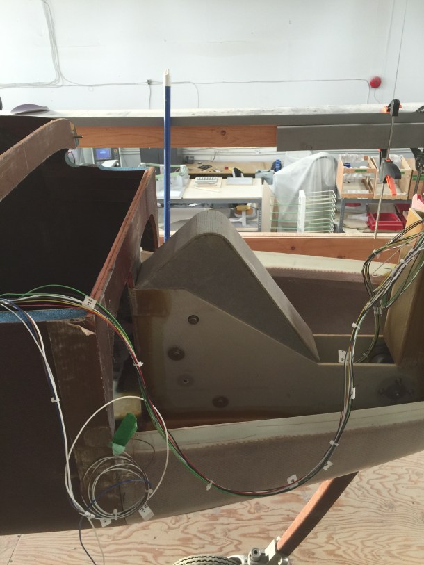
This is another pic of my feet, they are actually sitting in the dips in the floor. The height of the openings are around 13.2″ and my shoe measures 13.25″ so not a lot of room. Because I don’t have a lot of room to work with I have decided to finish the seat and make my cushion before I mount my rudder pedals. This means I will have to run as much of the systems that run down the sides of the fuse or at least make provisions for mounting them. I have been torn with the whole arm rest scenario on whether to make them removable or not. I want them removable for accessibility but also want the extra structure of them glassed to the thigh support. I think I have come up with a plan that will give me the best of both worlds. I will have to see if it works. When I bought my long-ez project it came with the Gerdes master cylinders. I was determined to use them and not buy new ones. Because of the fact that you can’t tip them you are limited to how you can orientate them.

I did’t want the original mod that was done to move the masters off the firewall. This is a pic that was taken from Mike Beasley’s site https://www.fototime.com/ftweb/bin/ft.dll/pictures?userid={6F024704-B6CF-4CA9-8F47-E86835AD7208}&AlbumId={0A85F8DF-EC4A-4192-B64A-1DF1D794EA7C}&GroupId={92F5E057-105B-48B4-9763-3A48B8B18C56}&nt=a He has a lot of great pics of his long-ez build.
What I really wanted was a masterpiece like Marco built at http://longezproject.blogspot.com for his long-ez. But my determination to use the master cylinders that I had just wouldn’t let me.

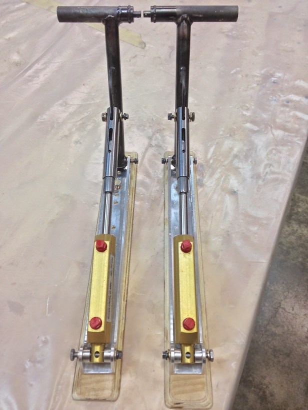
What I came up with was this.

To determine the mechanical advantage I did a simple test. I made a mock up of the pedal. I then took a the weight of an object.

I put the scale under the master cylinder and zeroed it. I then applied the weight to where force would be applied to the rudder pedal and got a new weight on the scale. It has a mechanical advantage of just over 2:1. I ran it by a few engineers that stopped by the shop and they concurred that it was correct.

Here it is in the brake applied position. The only reason I can use a setup like this is because I had to make the length of the rudder pedal longer so I wouldn’t be pressing on it with the arch of my foot. I did add some extra holes in the pedal so that if this set up doesn’t work i could still use the pedal with a matco master cylinder. My next step on the pedals is to order some material and build them but like I stated before I won’t determine their final position and install them until I have my seating locked down.

I moved on to the control system. Mine was already build by the proevious builder so that saved me some time. I did some lathe work to the CS106 & CS115. I needed them the right size to be able to press the bearings on to them. You need the bearings to have a slight interference fit otherwise there is no point in using bearings. If they are loose in the bearings you might as well just use bushings cause the will just spin in the bearing. The biggest task is to get the tubes round. That is why the cozy girrls centerless grind their parts.

I used my fancy inside tube cleaner 🙂

The outside of the tubes were cleaned on the lathe with some scotchbrite.

The holes were all debured. This tool does the inside of the tube as well as the outside. The little wing that sticks out is spring loaded so it compresses in so you can get it inside the tube.

I put all the 4130 parts into some metal prep to clean the surfaces. After this I made sure to not touch them without gloves on. Bare skin will guarantee corrosion in this state.

I mixed up some epoxy zinc cromate for priming the parts. I filled the tube with primer and dumped it out. This gives a thin coating on the inside of the tube.

The 4130 parts are wet installed into the aluminum tubes.

The CS112 is then pressed through the parts. It is cad plated so not much to be done on it for corrosion. After assembly of both ends the tube had primer poured into it, rolled around, then dumped out. The aluminum tubes are 6061 so I didn’t bother alodining them. I think the primer is is more than enough protection.

Bah, a victim of the game.

The parts were hung and prepped for priming.

The parts were then primed.

After removing the tape I put some WD-40 on the bare 4130 to prevent over oxidation or if you want you can just call it rust.

The bearings were pressed on to each end.

The CS109 & CS118 were bolted onto the bearings. I put a thin washer in between them to simulate the thickness of the glass that will be used for mounting them.

I then pulled a knife edge maneuver.

There is not a whole lot of data in the plans regarding the location of the CS109 & CS118. It is mostly dictated by the side console. So I made sure everything was square and marked their locations. I don’t believe you can get planer surfaced between the two of them by glassing them to the Side console first so I decided to mount them first using the aileron torque tube to hold them in position.

The CS109 & CS118 were floxed into position on the fuselage.

I also assembled the u joint to the torque tubes. You may have noticed that I am missing a pushrod from all these parts. I am waiting for the XM-3 rod ends to come in. They are a HM-4 with a hole to take a AN-3 bolt. I also ordered the steel CS-50s from Cozy Girrrls. Once those come in I will remake it with the new components.

